
A breakthrough continuous aqueous separation process that upgrades raw biogas and post-combustion industrial exhaust into pipeline-grade biomethane (RNG) and sequestration-ready CO₂ with zero exotic chemical reagents.
By deploying earth's most abundant fluid in high-efficiency aqueous compression, we eliminate chemical degradation, hazardous waste transport, and parasitic reboiler duties.

Conventional carbon capture relies on amines, glycols, or proprietary chemical reagents that degrade into toxic nitrosamines and corrosive degradation products. Our system runs entirely on water — eliminating hazardous chemical replacement, dangerous transport regulations, and environmental disposal liability.

Water is the most abundant fluid on planet earth. By operating at ambient to sub-ambient process temperatures, we exploit natural Henry's Law solubility differentials to capture CO₂, H₂S, and trace volatile organic contaminants without requiring thermal reboilers or exotic chemicals.

The system operates with zero net water consumption. Raw biogas and flue gas naturally carry water vapor; our proprietary compression and cooling cycle condenses H₂O vapor from the gas stream, rendering the facility water-neutral or even net water-positive in humid operating conditions.
A single integrated system that simultaneously purifies biogas into pipeline-grade biomethane (RNG) and captures a high-purity, sequesterable CO₂ stream without thermal parasitic loads.

A continuous dual-inlet aqueous mass-transfer architecture separating raw biological and thermal exhaust gases into pipeline-spec biomethane and pipeline-ready CO₂ for permanent geologic storage.
From agricultural anaerobic digesters, landfills, and municipal wastewater treatment facilities.
From gasifiers, biomass-to-power, waste-to-energy incineration, and industrial heating/steam boilers.
Under engineered pressure, recirculating water selectively dissolves acidic CO₂ and H₂S molecules at orders of magnitude higher rates than insoluble methane (CH₄), completely eliminating hazardous amine replenishment, chemical reboilers, and toxic solvent degradation.
Direct utility pipeline injection, CNG transportation fuel, or on-site clean distributed power.
Concentrated, pure CO₂ stream ready for pipeline transport, Class VI deep injection, or permanent rock mineralization.
Raw biogas from digesters and landfills, as well as post-combustion exhaust gases from gasifiers, biomass-to-power facilities, and waste incineration, are compressed directly with recirculating aqueous solution, absorbing compression heat isothermally.
Under engineered absorption pressures and geothermally assisted cooling, acidic gases (CO₂ and H₂S) dissolve into the liquid phase at orders of magnitude higher rates than non-acidic methane (CH₄) with zero toxic amine reagents.
Insoluble biomethane exits the separation column at >99% methane purity, meeting interstate pipeline specifications and CNG transportation standards without secondary chemical polishing.
The CO₂-saturated aqueous stream undergoes controlled pressure reduction, flashing a pure, pipeline-ready CO₂ product stream dewatered and compressed for deep saline aquifer injection, basalt mineralization, permanent Class VI storage, or EOR.
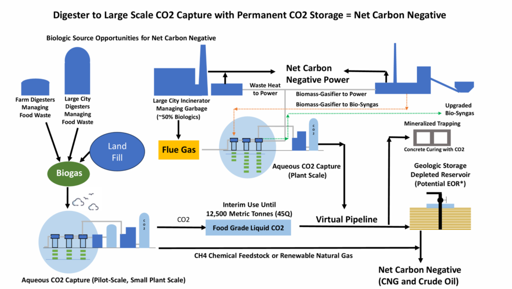
From agricultural anaerobic digesters and landfill biomethane to heavy industrial and power emissions abatement.
This is biogas, landfill gas, and biomass to power. Waste to power via incineration of garbage is biomass to power. Biologics includes bio-energy with carbon capture and sequestration (BECCS), a big term. BECCS includes permanent storage (geologic storage or mineralized storage). This all falls under another term which is carbon dioxide removal (CDR) from the biosphere indirectly moving the CO2 from the air to biologics to storage.
This is removing CO2 from power generating systems like coal, diesel, and natural gas fired power plants. This can be steam plants, natural gas fired turbines, or turbine plants linked to steam plant (called combined cycle). This process can operate well in this setting because there is typically waste heat that can be used for additional power recovery.
This is removing CO2 from industrial settings like data centers, incinerators, refineries, cement, smelting, glass manufacture, steam plants for heating, etc. This process can operate well in this setting especially if there is excess waste heat or the potential for heat integration. The waste heat can be used for additional power recovery.
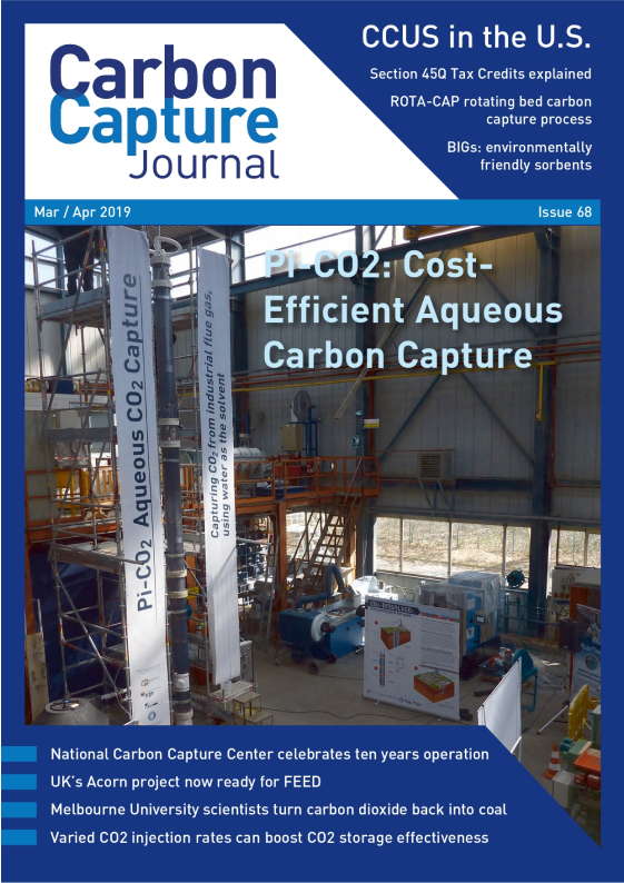
Featured in the leading international publication Carbon Capture Journal, detailing the thermodynamic simulation, lifecycle energy balance, and pilot performance of the patented PI-CO₂ system.
To capture and separate acid gases (CO₂ and H₂S) and siloxanes with zero exotic chemicals. Submit your site specifications for an engineering sizing simulation.